
'board_android-IoT/arduino_esp8266_esp32'에 해당되는 글 6건
- 2024.11.16 :: Conditional compile for ESP32 and ESP32S3
- 2023.06.15 :: Arduino - ADC voltage measurement using Aref
- 2021.08.22 :: Arduino External Interrup + Button
- 2021.08.13 :: STM32 CPU and 7Segment interface
- 2021.05.14 :: ESP8266-weather(temperature_humidity) station
- 2021.05.05 :: MINIDK, ESP8266-weather(temperature_humidity) station
// Source code in Arduino IDE
#ifdef CONFIG_IDF_TARGET_ESP32
#warning "[ESP32]"
#elif CONFIG_IDF_TARGET_ESP32S3
#warning "[ESP32S3]"
#endif
1. if select ESP32
> compile result:
....: warning: #warning "[ESP32]" [-Wcpp]
#warning "[ESP32]"
^~~~~~~
2. if select ESP32S3
- In arduino IDE, Menu: Tools-> Board -> ESP32 -> ESP32S3
...warning: #warning "[ESP32S3]" [-Wcpp]
#warning "[ESP32S3]"
^~~~~~~
Reference:
What is the specific #if defined(ARDUINO_ARCH_ESP32) for ESP32-S2, ESP32-S3, ESP32-C3?
as title. what is the specific #if defined(ARDUINO_ARCH_ESP32) for ESP32-S2, ESP32-S3, ESP32-C3? I want to do something only if ESP32-S2 is used for example.
community.platformio.org
'board_android-IoT > arduino_esp8266_esp32' 카테고리의 다른 글
| Arduino - ADC voltage measurement using Aref (0) | 2023.06.15 |
|---|---|
| Arduino External Interrup + Button (0) | 2021.08.22 |
| STM32 CPU and 7Segment interface (0) | 2021.08.13 |
| ESP8266-weather(temperature_humidity) station (0) | 2021.05.14 |
| MINIDK, ESP8266-weather(temperature_humidity) station (0) | 2021.05.05 |
- 아두이노 우노의 3.3V 핀을 A0에 연결해서 전압측정함.
>측정시 5V의 실제 전압은 4.65V가 나와서 (PC USB PORT <-> UNO) 이 값으로 Aref 핀에 연결하고 측정함.
(이렇게 해야 정확한 값이 측정됨)
| 16:18:42.132 -> digital value = 742, Aref:4.64, ADC voltage = 3.36 16:18:43.188 -> digital value = 743, Aref:4.64, ADC voltage = 3.36 16:18:44.242 -> digital value = 740, Aref:4.65, ADC voltage = 3.36 16:18:45.312 -> digital value = 742, Aref:4.64, ADC voltage = 3.36 16:18:46.352 -> digital value = 743, Aref:4.64, ADC voltage = 3.36 16:18:47.423 -> digital value = 742, Aref:4.62, ADC voltage = 3.35 16:18:48.480 -> digital value = 742, Aref:4.64, ADC voltage = 3.36 |
- Aref 전압을 입력받아서 정확한 값 측정,
|
int sensorPin = A0; // input pin for the potentiometer
int digitalValue = 0;// variable to store the value coming from the sensor
void setup() {
Serial.begin(9600);
// 아날로그 입력 핀을 읽기 전에 아날로그 기준 값을 외부 전원을
// 사용하는 것으로 설정합니다:
}
void loop() {
// analogReference(EXTERNAL);
delay(10);
digitalValue = analogRead(sensorPin);// read the value from the analog channel
Serial.print("digital value = ");
Serial.print(digitalValue); //print digital value on serial monitor
float voltage = readAref();
Serial.print(", Aref:");
Serial.print(voltage);
float ADC_voltage = voltage * (float)digitalValue / (float)1024;
Serial.print(", ADC voltage = ");
Serial.println( ADC_voltage ); //print digital value on serial monitor
delay(1000);
}
//
// Function readAref
//
// Reads AREF (when external voltage is supplied).
// When the AREF pin is open, a value of 1.1V is returned.
// This function is only valid for a voltage at AREF of 1.1 to 5V.
//
// The calculations can be translated for integers to prevent
// use of float.
// Only for the Arduino Uno, Nano, Pro Micro at this moment.
// Experimental, no guarantees.
// public domain
//
float readAref (void) {
float volt;
#if defined (__AVR_ATmega8__)
#elif defined (__AVR_ATmega168__)
#elif defined (__AVR_ATmega168A__)
#elif defined (__AVR_ATmega168P__)
#elif defined (__AVR_ATmega328__)
#elif defined (__AVR_ATmega328P__)
// set reference to AREF, and mux to read the internal 1.1V
// REFS1 = 0, REFS0 = 0, MUX3..0 = 1110
ADMUX = _BV(MUX3) | _BV(MUX2) | _BV(MUX1);
// Enable the ADC
ADCSRA |= _BV(ADEN);
// Wait for voltage to become stable after changing the mux.
delay(20);
// Start ADC
ADCSRA |= _BV(ADSC);
// wait for the ADC to finish
while (bit_is_set(ADCSRA,ADSC));
// Read the ADC result
// The 16-bit ADC register is 'ADC' or 'ADCW'
unsigned int raw = ADCW;
// Calculate the Aref.
volt = 1.1 / (float) raw * 1024.0;
#elif defined (__AVR_ATmega32U4__)
#elif defined (__AVR_ATmega1280__) || defined (__AVR_ATmega2560__)
#endif
// Try to return to normal.
analogReference(EXTERNAL);
analogRead(A0); // the mux is set, throw away ADC value
delay(20); // wait for voltages to become stable
return volt;
}
|
'board_android-IoT > arduino_esp8266_esp32' 카테고리의 다른 글
| Conditional compile for ESP32 and ESP32S3 (0) | 2024.11.16 |
|---|---|
| Arduino External Interrup + Button (0) | 2021.08.22 |
| STM32 CPU and 7Segment interface (0) | 2021.08.13 |
| ESP8266-weather(temperature_humidity) station (0) | 2021.05.14 |
| MINIDK, ESP8266-weather(temperature_humidity) station (0) | 2021.05.05 |
https://create.arduino.cc/projecthub/ronbentley1/button-switch-using-an-external-interrupt-7879df
Button Switch Using An External Interrupt
There are numerous examples of how to connect button switches via an external interrupt. This example offers an alternative approach. By ronbentley1.
create.arduino.cc
https://m.blog.naver.com/PostView.naver?isHttpsRedirect=true&blogId=yuyyulee&logNo=220310875023
[아두이노 강좌] 23. Interrupt(인터럽트) (3) - 인터럽트 함수 알아보기
지난 시간에 스위치를 누를 때마다 LED가 켜고 꺼지는 예제를 인터럽트를 이용한 소스로 구현해 봤었다....
blog.naver.com
https://learn.adafruit.com/adafruit-proto-shield-arduino?view=all
Adafruit Proto Shield for Arduino
This is a design for an open-source prototyping shield for Arduino NG/Diecimila. It has tons of cool features, to make prototyping on your Arduino easy.
learn.adafruit.com
http://www.martyncurrey.com/keypads/
Keypads and Button Switches on the Arduino | Martyn Currey
Digial keypad on the left. Analogue keypad on the right. When I first started building the dropController and the camController I could not find suitable navigation keypads, the ones I did find were expensive or not really suitable, so I built my own. Thes
www.martyncurrey.com
https://forum.arduino.cc/t/4x4-matrix-keypad-and-interrupt/460003
4x4 matrix keypad and interrupt
Hello, how can I exit a loop when I press the button ( 2 or 8 ) on the keypad. Is possible to using functions attachInterrupt()? I have ArduinoMega 2560. #include const byte ROWS = 4; const byte COLS = 4; char keys[ROWS][COLS] = { {'1','2','3'
forum.arduino.cc
https://circuitdigest.com/microcontroller-projects/arduino-interrupt-tutorial-with-examples
Arduino Interrupts Tutorial
Arduino Interrupts Tutorial
circuitdigest.com
https://forum.arduino.cc/t/keypad-without-keypad-library/656198/2
keypad without keypad library
Hello, I tried creating a code for a 4X4 keypad without the keypad library. Unfortunately it doesn’t perfectly work. I’m sure the witring is correct and it is normal if my pins are not in INPUT_PULLUP because I wired real resistors in my wiring. The bu
forum.arduino.cc
GPIO expander
https://m.blog.naver.com/PostView.naver?isHttpsRedirect=true&blogId=specialist0&logNo=220704124150
MCP23017 I/O Expander (STM32F051)
MCU를 사용하다가 입출력 포트가 부족할 때, I/O expander IC를 사용하면 입출력 포트를 늘릴 수 있...
blog.naver.com
'board_android-IoT > arduino_esp8266_esp32' 카테고리의 다른 글
| Conditional compile for ESP32 and ESP32S3 (0) | 2024.11.16 |
|---|---|
| Arduino - ADC voltage measurement using Aref (0) | 2023.06.15 |
| STM32 CPU and 7Segment interface (0) | 2021.08.13 |
| ESP8266-weather(temperature_humidity) station (0) | 2021.05.14 |
| MINIDK, ESP8266-weather(temperature_humidity) station (0) | 2021.05.05 |
- 선연결 테스트용
https://create.arduino.cc/projecthub/SAnwandter1/programming-4-digit-7-segment-led-display-2d33f8
Programming 4 Digit 7 Segment LED Display
Writing in a 4 digit 7 segment LED display. By SAnwandter1.
create.arduino.cc
- 효율적인 프로그램 코딩용
https://popcorn16.tistory.com/164
[아두이노] 4자리 7세그먼트 사용법 및 예제 - 카운터, 스톱워치
[Arduino] 7세그먼트 기초 사용법 7세그먼트 사용법에 이은 4자리 7 Segment 기초 사용법 포스팅입니다. 아두이노 보드 구성, 숫자 9876을 표시하는 방법, 카운터 만들기, 스톱워치 만들기를 직접 해보
popcorn16.tistory.com


| Digit to display |
A | B | C | D | E | F | G |
| 0 | 1 | 1 | 1 | 1 | 1 | 1 | 0 |
| 1 | 0 | 1 | 1 | 0 | 0 | 0 | 0 |
| 2 | 1 | 1 | 0 | 1 | 1 | 0 | 1 |
| 3 | 1 | 1 | 1 | 1 | 0 | 0 | 1 |
| 4 | 0 | 1 | 1 | 0 | 0 | 1 | 1 |
| 5 | 1 | 0 | 1 | 1 | 0 | 1 | 1 |
| 6 | 1 | 0 | 1 | 1 | 1 | 1 | 1 |
| 7 | 1 | 1 | 1 | 0 | 0 | 0 | 0 |
| 8 | 1 | 1 | 1 | 1 | 1 | 1 | 1 |
| 9 | 1 | 1 | 1 | 1 | 0 | 1 | 1 |
| A | 1 | 1 | 1 | 0 | 1 | 1 | 1 |
| b | 0 | 0 | 1 | 1 | 1 | 1 | 1 |
| C | 1 | 0 | 0 | 1 | 1 | 1 | 0 |
| d | 0 | 1 | 1 | 1 | 1 | 0 | 1 |
| E | 1 | 0 | 0 | 1 | 1 | 1 | 1 |
| F | 1 | 0 | 0 | 0 | 1 | 1 | 1 |
// 핀 번호 선언
int pos_pins[] = {8,11,12,7}; // 몇번째 세그먼트
int num_of_pos = 4;
int pins[] = {9,13,5,3,2,10,6,4}; // 세그먼트 a, b, c, d, e, f, g, dp
int num_of_pins = 8;
int delaytime = 5;

// 세그먼트에 표시 할 숫자
bool segment[10][8] = {
  {true, true, true, true, true, true, false, false}, //0
  {false, true, true, false, false, false, false, false}, //1
  {true, true, false, true, true, false, true, false}, //2
  {true, true, true, true, false, false, true, false}, //3
  {false, true, true, false, false, true, true, false}, //4
  {true, false, true, true, false, true, true, false}, //5
  {true, false, true, true, true, true, true, false}, //6
  {true, true, true, false, false, false, false, false}, //7
  {true, true, true, true, true, true, true, false}, //8
  {true, true, true, true, false, true, true, false} //9
};

void setup() {
  for(int i=0; i<num_of_pos; i++) {
     pinMode(pos_pins[i], OUTPUT);
  }
  for(int i=0; i<num_of_pins; i++) {
    pinMode(pins[i], OUTPUT);
  }
}

void loop() {
  int num[] = {9, 8, 7, 6};
  digits_4_seven_segment(num);
}

// 원하는 위치에 표시되도록 set
void set_position(int pos){
  for(int i = 0; i < 4; i++) {
    if(i + 1 == pos){
      digitalWrite(pos_pins[i], LOW);
    } else {
      digitalWrite(pos_pins[i], HIGH);
    }
  }
}

// 원하는 숫자 표시
void set_number(int number){
  for(int i=0;i<num_of_pins;++i){
    segment[number][i] ? digitalWrite(pins[i], HIGH) : digitalWrite(pins[i], LOW);
  }
}

// 원하는 위치, 원하는 숫자를 표시
void set_seven_segment(int pos, int number){
  set_position(pos);
  set_number(number);
}

// 입력된 4자리 숫자를 세그먼트에 표시
void digits_4_seven_segment(int num[]){
  for(int i=0;i<num_of_pos;++i){
    set_seven_segment(i+1,num[i]);
    delay(delaytime);
  }
}
- 기타 SPI통신 이용:
STM32 - SPI통신 MAX7219 7-segment 모듈
통신 방법 : SPI (최대속도 : 10Mhz) 작동 전압 : 4.0~5.5 환경 : P-NUCLEO-WB55 개발 보드, Atollic TrueSTUDIO [동작] 16 비트 데이터 포맷 사용 (D15~D12 사용 X) D11~D8 ADDRESS(명령어 역할), D7~D0 DATA(M..
rs29.tistory.com

- Interfacing 7 segment display with stm32f103 microcontroller
https://www.engineersgarage.com/stm32-microcontroller-7-segment-interface/
Interfacing 7 segment display with stm32f103 microcontroller
This tutorial is about interfacing 7 segment led display with stm32 microcontroller using keil arm mdk 5 with stm32 HAL libraries for code compilation. Stm32cubemx is used to initialize the stm32f103c8t6 microcontroller peripherals/variables pins, operati
www.engineersgarage.com
'board_android-IoT > arduino_esp8266_esp32' 카테고리의 다른 글
| Conditional compile for ESP32 and ESP32S3 (0) | 2024.11.16 |
|---|---|
| Arduino - ADC voltage measurement using Aref (0) | 2023.06.15 |
| Arduino External Interrup + Button (0) | 2021.08.22 |
| ESP8266-weather(temperature_humidity) station (0) | 2021.05.14 |
| MINIDK, ESP8266-weather(temperature_humidity) station (0) | 2021.05.05 |
- 알리익스프레스에서 구입했으나 자료가 없어서 결국 DIYMALL 사이트에서 찾은 구글드라이브 링크도
자료가 맞지않아서 esp8266과 oled display소스의 테스트 샘플을 보고 DIYmall의 구글드라이브 테스트 소스를
수정해서 동작하게 소스를 수정할수 있었습니다.
(Source code of DIYMALL was not suitable for working. So I modified source codes of DIYMALL. After all, OLED display can display temperature and humidity from BME280 sensor through I2C interfaces. )
#ESP8266 #ESP32 #weather_station #arduino #I2C
read temperature and humidity with esp8266 and one module(temperature, humidity)
1. product link:
18.52€ |MiniDK – Kit de Station météo ESP8266, panneau de développement, écran OLED 0.96, capteur de température et d'h
Achetez malin, vivez mieux! Aliexpress.com
fr.aliexpress.com
- 판매사이트의 사진 , MiniDK 보드와 BME280, OLED display 연결선을 보여줍니다(I2C)
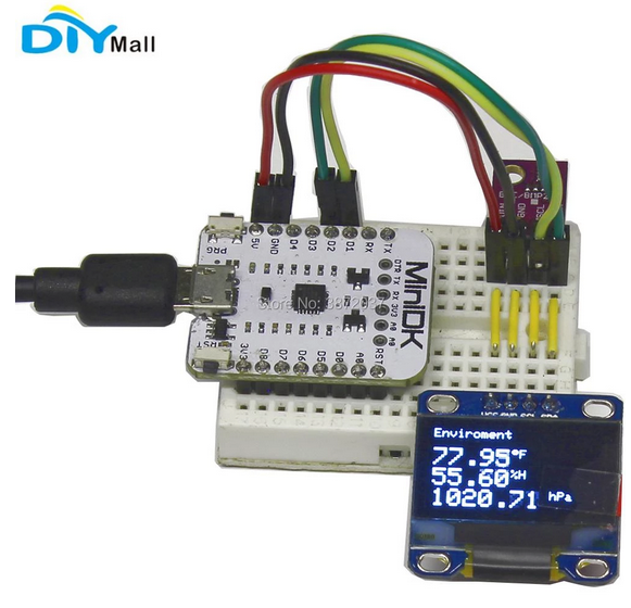

-실제 연결한 선
>I2C는 공통연결이라 선을 공유함. (VCC[5V],GND, D2,D1 -->VCC,GND,SCL,SCA)--VCC,GND,SCL,SDA

A.1 BME280 test source
A.1.1 link
- lastminuteengineers.com/bme280-esp8266-weather-station/
Create A Simple ESP8266 Weather Station With BME280
Learn to interface BME280 Sensor with ESP8266 NodeMCU, Display Temperature, Humidity, Pressure & Altitude on Web Server & Dynamically load data with AJAX
lastminuteengineers.com
A.1.2 test source
A.2. OLED display test with ESP8266
randomnerdtutorials.com/esp8266-0-96-inch-oled-display-with-arduino-ide/
ESP8266 0.96 inch OLED Display with Arduino IDE | Random Nerd Tutorials
This guide shows how to use the 0.96 inch SSD1306 OLED display with ESP8266 using Arduino IDE. Learn how to write text, set different fonts, draw shapes and display bitmaps images.
randomnerdtutorials.com
A.3. mini-DK 판매사이트의 자료
- 구글 드라이브 링크:
https://drive.google.com/open?id=1ClXhsZ9YhpIe02s92lyQP42AXGGmPCmo
MiniDK-Weather-station-kit-DIY0074.zip
drive.google.com
A.3.2 판매자 링크:
www.diymalls.com/MiniDK-Weather-Station-Kit?search=minidk
MiniDK Weather Station Kit
Package Includes: 1 X MiniDK 1 X 0.96 OLED White 1 X 170 Tie Point Breadboard 1 X 65pcs Jump Wire 1 X Micro USB Cable 1 X BME280 Pressure Humidity Temperature Sensor Document link: https://drive.google.com/open?id=1ClXhsZ9YhpIe02s92lyQP42AXGGmPCmo
www.diymalls.com
'board_android-IoT > arduino_esp8266_esp32' 카테고리의 다른 글
| Conditional compile for ESP32 and ESP32S3 (0) | 2024.11.16 |
|---|---|
| Arduino - ADC voltage measurement using Aref (0) | 2023.06.15 |
| Arduino External Interrup + Button (0) | 2021.08.22 |
| STM32 CPU and 7Segment interface (0) | 2021.08.13 |
| MINIDK, ESP8266-weather(temperature_humidity) station (0) | 2021.05.05 |
MINIDK, Weather station using BME280 and OLED display
- 알리익스프레스에서 구입했으나 자료가 없어서 결국 DIYMALL 사이트에서 찾은 구글드라이브 링크도
자료가 맞지않아서 esp8266과 oled display소스의 테스트 샘플을 보고 DIYmall의 구글드라이브 테스트 소스를
수정해서 동작하게 소스를 수정할수 있었습니다.
https://drive.google.com/open?id=1ClXhsZ9YhpIe02s92lyQP42AXGGmPCmo
(Source code of DIYMALL was not suitable for working. So I modified source codes of DIYMALL. After all, OLED display can display temperature and humidity from BME280 sensor through I2C interfaces. )
#ESP8266 #ESP32 #weather_station #arduino #I2C
read temperature and humidity with esp8266 and one module(temperature, humidity)
1. product link:
18.52€ |MiniDK – Kit de Station météo ESP8266, panneau de développement, écran OLED 0.96, capteur de température et d'h
Achetez malin, vivez mieux! Aliexpress.com
fr.aliexpress.com
http://www.diymalls.com/DIYmall-Category-DIY-Kit/MiniDK-Weather-Station-Kit
MiniDK Weather Station Kit
Package Includes: 1 X MiniDK 1 X 0.96 OLED White 1 X 170 Tie Point Breadboard 1 X 65pcs Jump Wire 1 X Micro USB Cable 1 X BME280 Pressure Humidity Temperature Sensor Document link: https://drive.google.com/open?id=1ClXhsZ9YhpIe02s92lyQP42AXGGmPCmo
www.diymalls.com
- 판매사이트의 사진 , MiniDK 보드와 BME280, OLED display 연결선을 보여줍니다(I2C)


-실제 연결한 선
>I2C는 공통연결이라 선을 공유함. (VCC[5V],GND, D2,D1 -->VCC,GND,SCL,SCA)--VCC,GND,SCL,SDA

A.1 BME280 test source
A.1.1 link
- lastminuteengineers.com/bme280-esp8266-weather-station/
Create A Simple ESP8266 Weather Station With BME280
Learn to interface BME280 Sensor with ESP8266 NodeMCU, Display Temperature, Humidity, Pressure & Altitude on Web Server & Dynamically load data with AJAX
lastminuteengineers.com
A.1.2 test source
A.2. OLED display test with ESP8266
randomnerdtutorials.com/esp8266-0-96-inch-oled-display-with-arduino-ide/
ESP8266 0.96 inch OLED Display with Arduino IDE | Random Nerd Tutorials
This guide shows how to use the 0.96 inch SSD1306 OLED display with ESP8266 using Arduino IDE. Learn how to write text, set different fonts, draw shapes and display bitmaps images.
randomnerdtutorials.com
A.3. mini-DK 판매사이트의 자료
- 구글 드라이브 링크:
https://drive.google.com/open?id=1ClXhsZ9YhpIe02s92lyQP42AXGGmPCmo
MiniDK-Weather-station-kit-DIY0074.zip
drive.google.com
A.3.2 판매자 링크:
www.diymalls.com/MiniDK-Weather-Station-Kit?search=minidk
MiniDK Weather Station Kit
Package Includes: 1 X MiniDK 1 X 0.96 OLED White 1 X 170 Tie Point Breadboard 1 X 65pcs Jump Wire 1 X Micro USB Cable 1 X BME280 Pressure Humidity Temperature Sensor Document link: https://drive.google.com/open?id=1ClXhsZ9YhpIe02s92lyQP42AXGGmPCmo
www.diymalls.com
'board_android-IoT > arduino_esp8266_esp32' 카테고리의 다른 글
| Conditional compile for ESP32 and ESP32S3 (0) | 2024.11.16 |
|---|---|
| Arduino - ADC voltage measurement using Aref (0) | 2023.06.15 |
| Arduino External Interrup + Button (0) | 2021.08.22 |
| STM32 CPU and 7Segment interface (0) | 2021.08.13 |
| ESP8266-weather(temperature_humidity) station (0) | 2021.05.14 |