
- 선연결 테스트용
https://create.arduino.cc/projecthub/SAnwandter1/programming-4-digit-7-segment-led-display-2d33f8
Programming 4 Digit 7 Segment LED Display
Writing in a 4 digit 7 segment LED display. By SAnwandter1.
create.arduino.cc
- 효율적인 프로그램 코딩용
https://popcorn16.tistory.com/164
[아두이노] 4자리 7세그먼트 사용법 및 예제 - 카운터, 스톱워치
[Arduino] 7세그먼트 기초 사용법 7세그먼트 사용법에 이은 4자리 7 Segment 기초 사용법 포스팅입니다. 아두이노 보드 구성, 숫자 9876을 표시하는 방법, 카운터 만들기, 스톱워치 만들기를 직접 해보
popcorn16.tistory.com
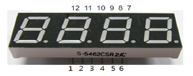

| Digit to display |
A | B | C | D | E | F | G |
| 0 | 1 | 1 | 1 | 1 | 1 | 1 | 0 |
| 1 | 0 | 1 | 1 | 0 | 0 | 0 | 0 |
| 2 | 1 | 1 | 0 | 1 | 1 | 0 | 1 |
| 3 | 1 | 1 | 1 | 1 | 0 | 0 | 1 |
| 4 | 0 | 1 | 1 | 0 | 0 | 1 | 1 |
| 5 | 1 | 0 | 1 | 1 | 0 | 1 | 1 |
| 6 | 1 | 0 | 1 | 1 | 1 | 1 | 1 |
| 7 | 1 | 1 | 1 | 0 | 0 | 0 | 0 |
| 8 | 1 | 1 | 1 | 1 | 1 | 1 | 1 |
| 9 | 1 | 1 | 1 | 1 | 0 | 1 | 1 |
| A | 1 | 1 | 1 | 0 | 1 | 1 | 1 |
| b | 0 | 0 | 1 | 1 | 1 | 1 | 1 |
| C | 1 | 0 | 0 | 1 | 1 | 1 | 0 |
| d | 0 | 1 | 1 | 1 | 1 | 0 | 1 |
| E | 1 | 0 | 0 | 1 | 1 | 1 | 1 |
| F | 1 | 0 | 0 | 0 | 1 | 1 | 1 |
// 핀 번호 선언
int pos_pins[] = {8,11,12,7}; // 몇번째 세그먼트
int num_of_pos = 4;
int pins[] = {9,13,5,3,2,10,6,4}; // 세그먼트 a, b, c, d, e, f, g, dp
int num_of_pins = 8;
int delaytime = 5;

// 세그먼트에 표시 할 숫자
bool segment[10][8] = {
  {true, true, true, true, true, true, false, false}, //0
  {false, true, true, false, false, false, false, false}, //1
  {true, true, false, true, true, false, true, false}, //2
  {true, true, true, true, false, false, true, false}, //3
  {false, true, true, false, false, true, true, false}, //4
  {true, false, true, true, false, true, true, false}, //5
  {true, false, true, true, true, true, true, false}, //6
  {true, true, true, false, false, false, false, false}, //7
  {true, true, true, true, true, true, true, false}, //8
  {true, true, true, true, false, true, true, false} //9
};

void setup() {
  for(int i=0; i<num_of_pos; i++) {
     pinMode(pos_pins[i], OUTPUT);
  }
  for(int i=0; i<num_of_pins; i++) {
    pinMode(pins[i], OUTPUT);
  }
}

void loop() {
  int num[] = {9, 8, 7, 6};
  digits_4_seven_segment(num);
}

// 원하는 위치에 표시되도록 set
void set_position(int pos){
  for(int i = 0; i < 4; i++) {
    if(i + 1 == pos){
      digitalWrite(pos_pins[i], LOW);
    } else {
      digitalWrite(pos_pins[i], HIGH);
    }
  }
}

// 원하는 숫자 표시
void set_number(int number){
  for(int i=0;i<num_of_pins;++i){
    segment[number][i] ? digitalWrite(pins[i], HIGH) : digitalWrite(pins[i], LOW);
  }
}

// 원하는 위치, 원하는 숫자를 표시
void set_seven_segment(int pos, int number){
  set_position(pos);
  set_number(number);
}

// 입력된 4자리 숫자를 세그먼트에 표시
void digits_4_seven_segment(int num[]){
  for(int i=0;i<num_of_pos;++i){
    set_seven_segment(i+1,num[i]);
    delay(delaytime);
  }
}
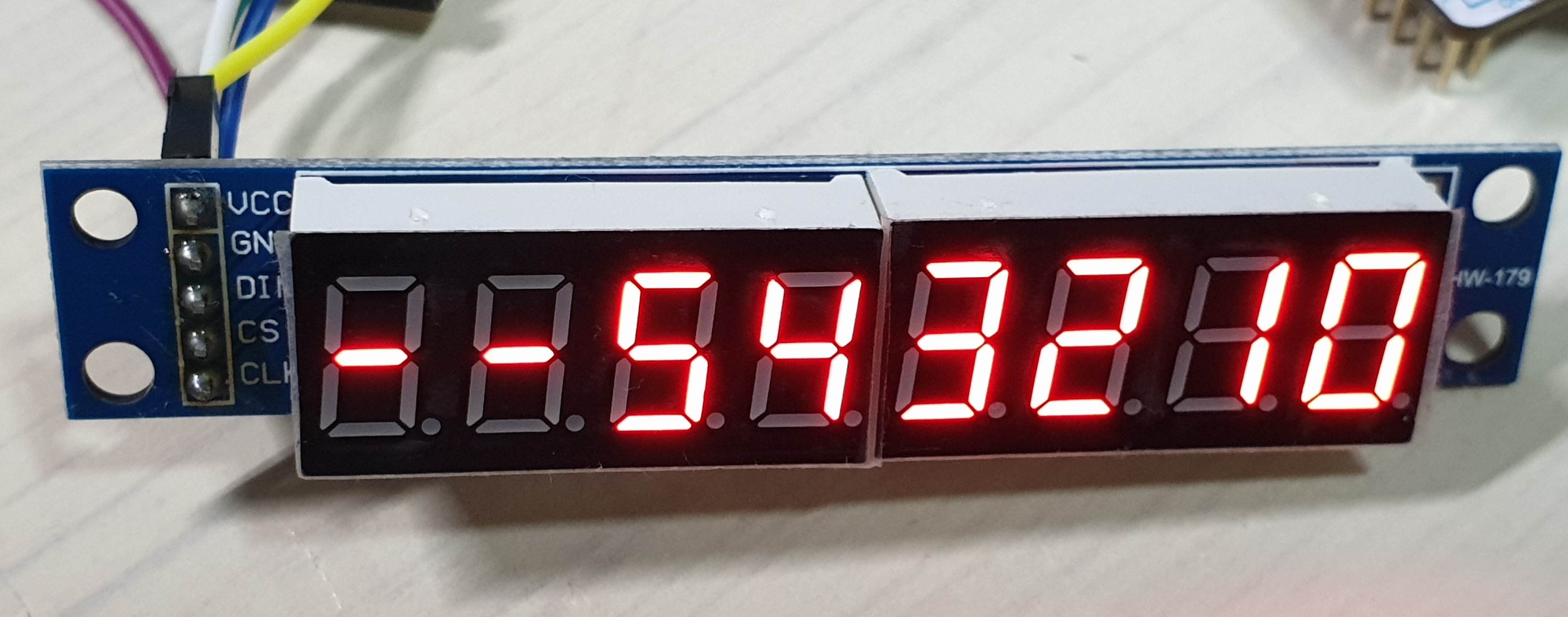
- 기타 SPI통신 이용:
STM32 - SPI통신 MAX7219 7-segment 모듈
통신 방법 : SPI (최대속도 : 10Mhz) 작동 전압 : 4.0~5.5 환경 : P-NUCLEO-WB55 개발 보드, Atollic TrueSTUDIO [동작] 16 비트 데이터 포맷 사용 (D15~D12 사용 X) D11~D8 ADDRESS(명령어 역할), D7~D0 DATA(M..
rs29.tistory.com
- Interfacing 7 segment display with stm32f103 microcontroller
https://www.engineersgarage.com/stm32-microcontroller-7-segment-interface/
Interfacing 7 segment display with stm32f103 microcontroller
This tutorial is about interfacing 7 segment led display with stm32 microcontroller using keil arm mdk 5 with stm32 HAL libraries for code compilation. Stm32cubemx is used to initialize the stm32f103c8t6 microcontroller peripherals/variables pins, operati
www.engineersgarage.com
'board_android-IoT > arduino_esp8266_esp32' 카테고리의 다른 글
| Conditional compile for ESP32 and ESP32S3 (0) | 2024.11.16 |
|---|---|
| Arduino - ADC voltage measurement using Aref (0) | 2023.06.15 |
| Arduino External Interrup + Button (0) | 2021.08.22 |
| ESP8266-weather(temperature_humidity) station (0) | 2021.05.14 |
| MINIDK, ESP8266-weather(temperature_humidity) station (0) | 2021.05.05 |