
'board_android-IoT/STM32F'에 해당되는 글 31건
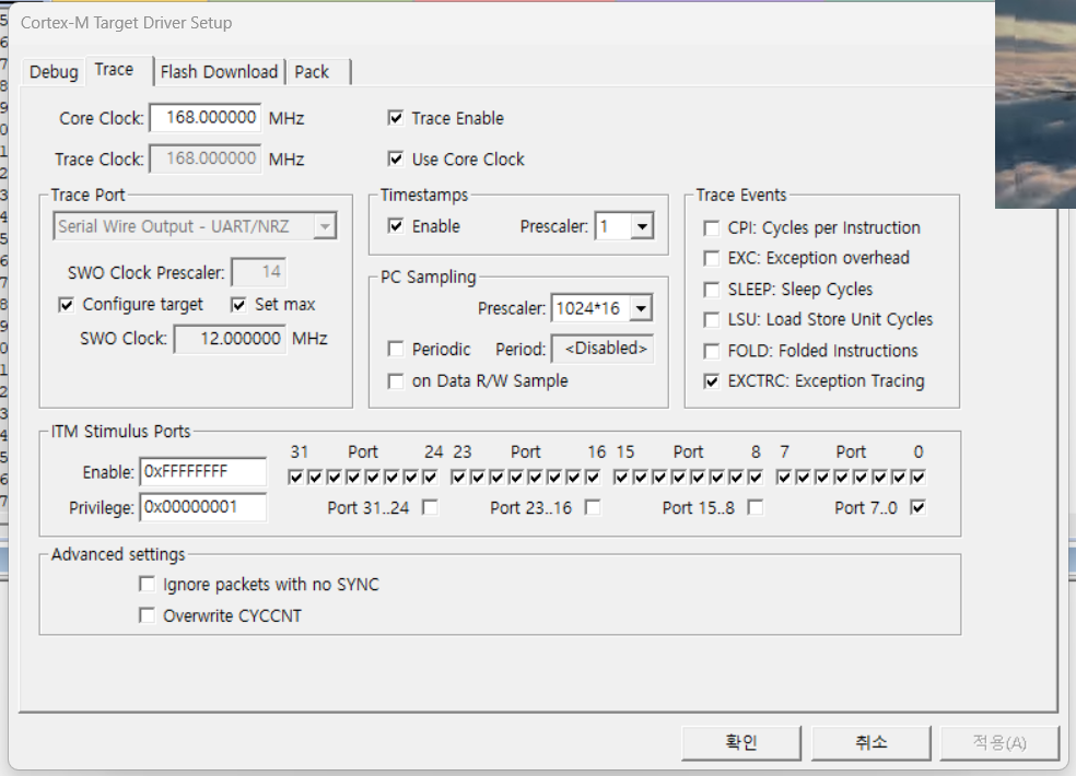
- 2024.07.23 :: SWO (Serial Wire Output) setting 2
- 2024.07.20 :: Porting STM32F1 Firmware to STM32F4
- 2024.07.10 :: CS5480 - Voltage, Current RMS calculation IC
- 2024.07.03 :: ADC conversion time calculation
- 2024.07.02 :: ADC interrupt reading
- 2024.07.01 :: STM32F, STM32F103 ADC reading , multiple reading
- main.c
| ... /* USER CODE BEGIN PV */ uint8_t g_bPortStatus = 0; uint8_t blueButtonStatus=0; /* USER CODE END PV */ /* Private function prototypes -----------------------------------------------*/ void SystemClock_Config(void); static void MX_GPIO_Init(void); static void MX_I2C1_Init(void); static void MX_I2S3_Init(void); static void MX_SPI1_Init(void); /* USER CODE BEGIN PFP */ /* USER CODE END PFP */ /* Private user code ---------------------------------------------------------*/ /* USER CODE BEGIN 0 */ void HAL_GPIO_EXTI_Callback(uint16_t GPIO_Pin) { if(GPIO_Pin == GPIO_PIN_0) { //HAL_GPIO_TogglePin(GPIOB, GPIO_PIN_0); //HAL_GPIO_TogglePin(GPIOD, GPIO_PIN_12); blueButtonStatus = ~blueButtonStatus ; } else if(GPIO_Pin == GPIO_PIN_1) { HAL_GPIO_TogglePin(GPIOB, GPIO_PIN_5); } else if(GPIO_Pin == GPIO_PIN_4) { HAL_GPIO_TogglePin(GPIOC, GPIO_PIN_6); } } // in Keil, redefinition of fpuc is necessary int fputc(int ch, FILE *f) { ITM_SendChar(ch); return(ch); } //in CubeIDE, redefinition of _write is ncessary int _write(int file, char *ptr, int len) { for(int i = 0; i < len; i++) { ITM_SendChar(*ptr++); } return len; } int k =0 , ret ; void ITM_SendString(char *s) { while(*s) ITM_SendChar(*s++); } uint8_t *data = "Hello World from USB CDC\n"; /* USER CODE END 0 */ /** * @brief The application entry point. * @retval int */ int main(void) { /* USER CODE BEGIN 1 */ /* USER CODE END 1 */ /* MCU Configuration--------------------------------------------------------*/ /* Reset of all peripherals, Initializes the Flash interface and the Systick. */ HAL_Init(); /* USER CODE BEGIN Init */ /* USER CODE END Init */ /* Configure the system clock */ SystemClock_Config(); /* USER CODE BEGIN SysInit */ /* USER CODE END SysInit */ /* Initialize all configured peripherals */ MX_GPIO_Init(); MX_I2C1_Init(); MX_I2S3_Init(); MX_SPI1_Init(); MX_USB_DEVICE_Init(); /* USER CODE BEGIN 2 */ /* USER CODE END 2 */ /* Infinite loop */ /* USER CODE BEGIN WHILE */ while (1) { /* USER CODE END WHILE */ /* USER CODE BEGIN 3 */ //HAL_GPIO_TogglePin(GPIOD, GPIO_PIN_12); if( blueButtonStatus == SET) HAL_GPIO_WritePin(GPIOD, GPIO_PIN_12 , 1) ; else HAL_GPIO_WritePin(GPIOD, GPIO_PIN_12 , 0) ; HAL_GPIO_TogglePin(GPIOD, GPIO_PIN_13); HAL_GPIO_TogglePin(GPIOD, GPIO_PIN_14); HAL_GPIO_TogglePin(GPIOD, GPIO_PIN_15); g_bPortStatus = HAL_GPIO_ReadPin(GPIOD, GPIO_PIN_12); printf("swo printf:%d\n", k++);//redefinition of fputc required k=k%10; ITM_SendString("0123456789\n"); ITM_SendChar('s'); HAL_Delay(500); ret =CDC_Transmit_FS(data, strlen(data)); HAL_Delay (1000); } /* USER CODE END 3 */ }// end of main |
'board_android-IoT > STM32F' 카테고리의 다른 글
| Keil, uVision , Compile size check (0) | 2024.10.12 |
|---|---|
| LTE modem sample (0) | 2024.09.20 |
| Porting STM32F1 Firmware to STM32F4 (0) | 2024.07.20 |
| CS5480 - Voltage, Current RMS calculation IC (0) | 2024.07.10 |
| ADC conversion time calculation (0) | 2024.07.03 |
Porting STM32F1 Firmware to STM32F4
Hey all, I want to port this https://github.com/ArduCAM/STM32/tree/master/STM32F103 package to use for an STM32F446RE development board. Can anyone offer any advice as to the best practices of accomplishing this? Would it be modifying mapping of GPIOs, c
community.st.com
Porting STM32F1 Firmware to STM32F4
- design guide

- comparison
'board_android-IoT > STM32F' 카테고리의 다른 글
| LTE modem sample (0) | 2024.09.20 |
|---|---|
| SWO (Serial Wire Output) setting (2) | 2024.07.23 |
| CS5480 - Voltage, Current RMS calculation IC (0) | 2024.07.10 |
| ADC conversion time calculation (0) | 2024.07.03 |
| ADC interrupt reading (0) | 2024.07.02 |
- CS5480 datasheet
https://statics.cirrus.com/pubs/proDatasheet/CS5480_F3.pdf
- CS5480 Evaluation board
https://statics.cirrus.com/pubs/rdDatasheet/CDB5480U_DB5.pdf
>CS5480
https://www.mouser.com/datasheet/2/76/CS5484-80-90_PB_201201-26892.pdf
Application Note/Using the CS5480/84/90 Energy Measurement IC with Rogowski Coil Current Sensors
https://statics.cirrus.com/pubs/appNote/AN365REV1.pdf
- CRD5463PM Power Monitor
https://statics.cirrus.com/pubs/rdDatasheet/CRD5463PM_RD2.pdf
- Application Note / CS5480/84/90 Measurement Accuracy vs. IEC Standards
https://www.manualsdir.com/manuals/466436/cirrus-logic-an362.html
Real time monitoring of High Voltage Transmission line conductor sag using RFID radar system
https://az817975.vo.msecnd.net/wm-418498-cmsimages/Saupec_2015_Papers_Combined.pdf
- CS5480-INZ price
https://www.digikey.in/en/products/detail/cirrus-logic-inc/cs5480-inz/2797392
> 1개당 5,600원 정도
- CS5480관련 제품 홍보 카달로그
https://statics.cirrus.com/pubs/brochure/energy_measurement_brochure_201201.pdf
BM1Z002FJ, AC Voltage Zero Cross Detection IC
https://www.rohm.com/products/power-management/ac-voltage-zero-cross-detection-ics/bm1z002fj-product
'board_android-IoT > STM32F' 카테고리의 다른 글
| SWO (Serial Wire Output) setting (2) | 2024.07.23 |
|---|---|
| Porting STM32F1 Firmware to STM32F4 (0) | 2024.07.20 |
| ADC conversion time calculation (0) | 2024.07.03 |
| ADC interrupt reading (0) | 2024.07.02 |
| STM32F, STM32F103 ADC reading , multiple reading (0) | 2024.07.01 |
ADC - conversion time 계산
Conversion time

According to the datasheet, the total conversion time is calculated as follows:
Tconv = Sampling time + 12.5 cycles
Example: With an ADCCLK = 14 MHz and a sampling time of 1.5 cycles: Tconv = 1.5 + 12.5 = 14 cycles = (14cycles/14MHz) = 1 µs

There is an entire article on the Conversion Time and Frequency calculation. You can read it
https://controllerstech.com/adc-conversion-time-frequency-calculation-in-stm32/
How to calculate ADC Conversrion Time and Frequency in STM32
ADC Conversion Time = Sampling Time + 12.5 Cycles. Here Sampling Time is something that you can choose during the setup in the CubeMX.
controllerstech.com

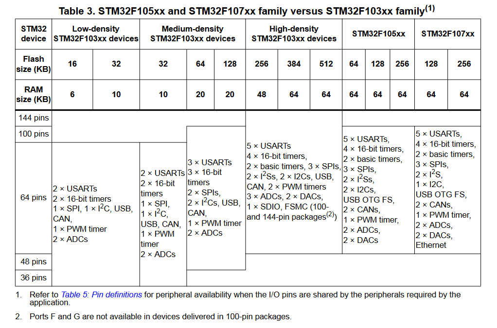
응용: STM32F107 , ADC clock:
- ADC clock : 12MHz
- 5.1 (Typ)~ 17.1(Max) us
- 5.1us , ADCCLK=12MHz, sampling time of 5.1us: Tconv = 1.5 + 12.5 = 14 clcyes = (14cycles/12MHz) = 1.16us

참고: STM32F103 datasheet :
https://www.google.com/url?sa=t&source=web&rct=j&opi=89978449&url=https://www.st.com/resource/en/datasheet/stm32f107vc.pdf&ved=2ahUKEwjbpejYxomHAxVXsVYBHZU5AtsQFnoECBoQAQ&usg=AOvVaw21INT5wnsKjGBpccQ4GItf

'board_android-IoT > STM32F' 카테고리의 다른 글
| Porting STM32F1 Firmware to STM32F4 (0) | 2024.07.20 |
|---|---|
| CS5480 - Voltage, Current RMS calculation IC (0) | 2024.07.10 |
| ADC interrupt reading (0) | 2024.07.02 |
| STM32F, STM32F103 ADC reading , multiple reading (0) | 2024.07.01 |
| STM32F ADC reading (Temperature sensor and Vrefint) (0) | 2024.06.29 |
https://m.blog.naver.com/jeon930429/222317966769
[STM32CubeIDE] ADC Interrupt
이번 포스팅 목적 'ADC Interrupt' ADC 사용을 Interrupt 방식으로 온도센서값 변환하기...
blog.naver.com
'board_android-IoT > STM32F' 카테고리의 다른 글
| CS5480 - Voltage, Current RMS calculation IC (0) | 2024.07.10 |
|---|---|
| ADC conversion time calculation (0) | 2024.07.03 |
| STM32F, STM32F103 ADC reading , multiple reading (0) | 2024.07.01 |
| STM32F ADC reading (Temperature sensor and Vrefint) (0) | 2024.06.29 |
| Boot mode Pin (1) | 2024.02.16 |
- 실행화면:
> Vrefint : 1705 -> 환산: 2.882 , PA0 ADC reading: 1.205
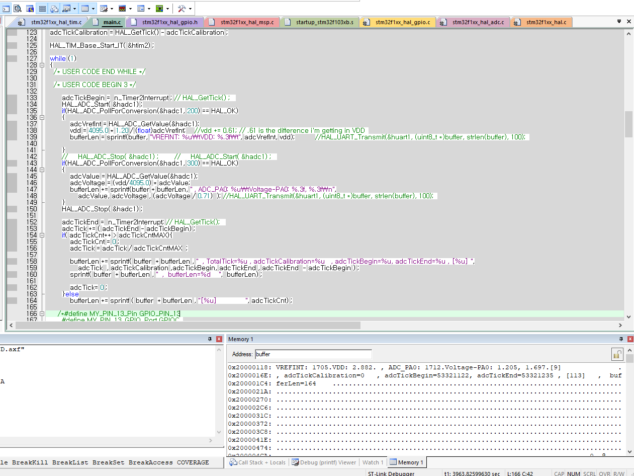
- main()함수 내부:
| /* Infinite loop */ /* USER CODE BEGIN WHILE */ adcTickCalibration = HAL_GetTick() ; while(HAL_ADCEx_Calibration_Start(&hadc1) != HAL_OK); //20240624 , ADC calibration , https://jeonhj.tistory.com/22 // while(HAL_ADCEx_Calibration_Start(&hadc2) != HAL_OK); //20240624 , ADC calibration , https://jeonhj.tistory.com/22 adcTickCalibration = HAL_GetTick() - adcTickCalibration ; HAL_TIM_Base_Start_IT( &htim2) ; while (1) { /* USER CODE END WHILE */ /* USER CODE BEGIN 3 */ adcTickBegin = n_Timer2Interrupt ; // HAL_GetTick() ; HAL_ADC_Start( &hadc1) ; if(HAL_ADC_PollForConversion(&hadc1, 200) == HAL_OK) { adcVrefInt = HAL_ADC_GetValue(&hadc1); vdd = 4095.0 * 1.20 / (float)adcVrefInt; //vdd += 0.61; // .61 is the difference i'm getting in VDD bufferLen = sprintf(buffer, "VREFINT: %u\tVDD: %.3f\t", adcVrefInt, vdd); //HAL_UART_Transmit(&huart1, (uint8_t *)buffer, strlen(buffer), 100); } // HAL_ADC_Stop( &hadc1) ; // HAL_ADC_Start( &hadc1) ; if(HAL_ADC_PollForConversion(&hadc1, 300) == HAL_OK) { adcValue = HAL_ADC_GetValue(&hadc1); adcVoltage = (vdd/4095.0) * adcValue; bufferLen += sprintf(buffer + bufferLen, " , ADC_PA0: %u\tVoltage-PA0: %.3f, %.3f\n", adcValue, adcVoltage , (adcVoltage / 0.71) ); //HAL_UART_Transmit(&huart1, (uint8_t *)buffer, strlen(buffer), 100); } HAL_ADC_Stop( &hadc1) ; adcTickEnd = n_Timer2Interrupt; // HAL_GetTick(); adcTick += ( adcTickEnd - adcTickBegin) ; if( adcTickCnt++ > adcTickCntMAX){ adcTickCnt = 0 ; adcTick = adcTick / adcTickCntMAX ; bufferLen += sprintf( buffer + bufferLen , " , TotalTick=%u , adcTickCalibration=%u , adcTickBegin=%u, adcTickEnd=%u , [%u] ", adcTick , adcTickCalibration ,adcTickBegin, adcTickEnd , adcTickEnd - adcTickBegin ) ; sprintf( buffer + bufferLen , " , bufferLen=%d ", bufferLen) ; adcTick= 0 ; }else bufferLen += sprintf ( buffer + bufferLen , "[%u] ", adcTickCnt) ; /*#define MY_PIN_13_Pin GPIO_PIN_13 #define MY_PIN_13_GPIO_Port GPIOC */ HAL_GPIO_WritePin( GPIOC, GPIO_PIN_13, GPIO_PIN_SET) ; HAL_Delay(500) ; HAL_GPIO_WritePin( GPIOC, GPIO_PIN_13, GPIO_PIN_RESET) ; HAL_Delay(500) ; // printf("Hello World") ; }//end of while /* USER CODE END 3 */ |
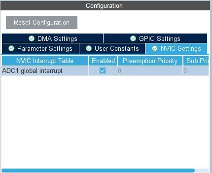
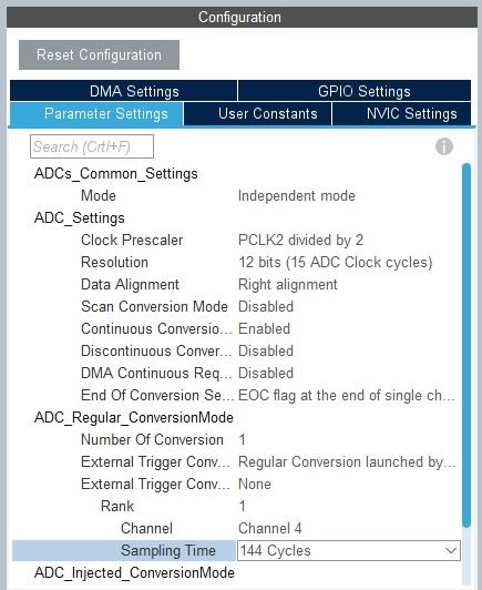
- CubeMX설정:

- TIM2


- 배터리 전압 관련 회로도: STM32F103

-Vrefint 관련 자료1:

- 자료2:
'board_android-IoT > STM32F' 카테고리의 다른 글
| ADC conversion time calculation (0) | 2024.07.03 |
|---|---|
| ADC interrupt reading (0) | 2024.07.02 |
| STM32F ADC reading (Temperature sensor and Vrefint) (0) | 2024.06.29 |
| Boot mode Pin (1) | 2024.02.16 |
| STM32F103Cx MCU major(timer, UART, EXTI) function entry names (1) | 2024.01.05 |